 Skip to content


Services / Pneumatic systems
Pneumatic systems engineering: design, analysis, tests and certification
Design, analysis, tests and certification reports for aircraft pneumatic systems (ATA 36): pressure drop, flow sharing, temperature, control, leak detection and duct loads. We issue the certification documents; you review them and submit them to the authority.
A complete pneumatic system package for the Embraer E2, 2014 to 2018: system design and analysis, leak detection design, system description (ATA 36), component qualification and pressurization test proposals, on the ground and in flight.
Pneumatic systems track record
- Embraer E2, 2014 to 2018Pneumatic system: design and analysis, leak detection design, system description (ATA 36), component qualification, pressurization test proposals on the ground and in flight.
- Models used by the manufacturerA validated thermal model and an exclusive FEA model created for the manufacturer’s use.
- Reports used in the safety assessmentThe delivered reports supported the safety assessment, and complex decisions were made without missing the deadline.
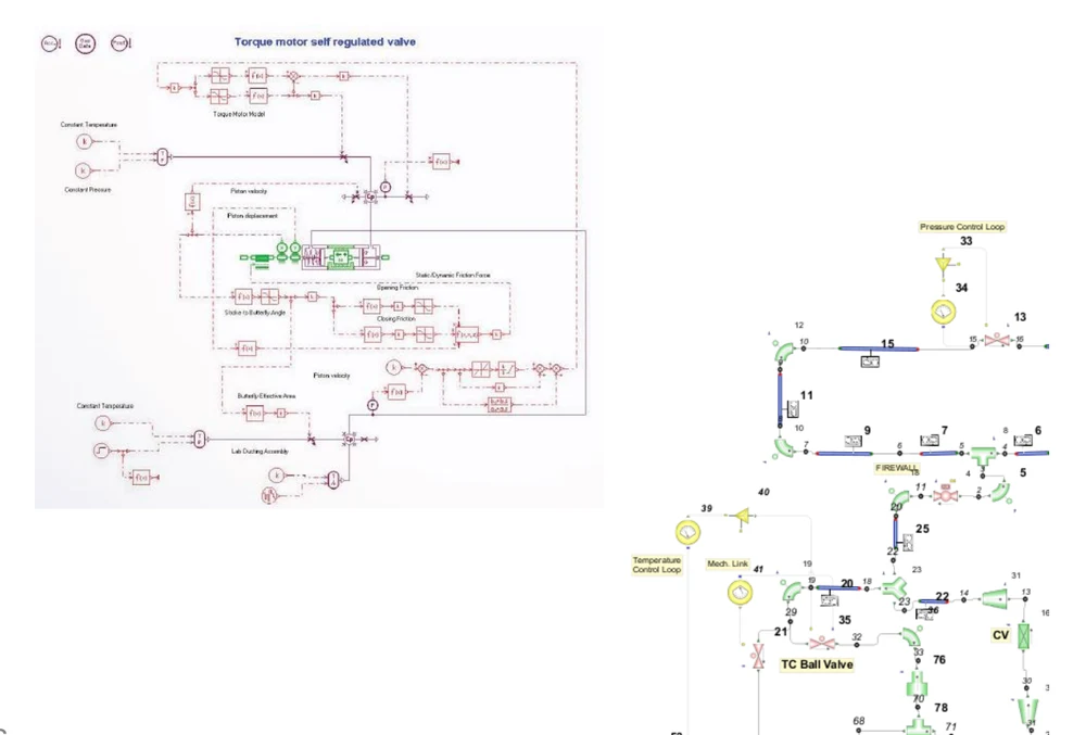
- Flow sharing and instabilities solvedAMESim and FloMaster models of a laboratory plant and of the aircraft system, validated, in steady state and transient.
- Leak and overheat detectionCompartment temperatures, detection times and overheat detector setpoints for each region.
- Embraer, 1997 to 2007E190: focus on the pneumatic system, with work on ECS and icing certification.
Complete packages, from requirements to certification reports
We prefer whole, long-term programs to isolated tasks: ATS responsible for design support, tests and the certification documents.
What a package covers
System design and analysis, leak detection design, system description, safety assessment inputs, test proposals, component qualification review and the compliance reports. We issue these documents ourselves, from analysis or test results. You review them and submit them to the authorities. This is our differentiator.
One team for the whole program
At least one associate senior engineer stays assigned from the first requirement to the last report, so decisions, test points and evidence stay consistent. When needed, an engineer works full time on site with your team.
An example: Embraer E2
2014 to 2018. The pneumatic system package of the E2: design and analysis, leak detection design, system description (ATA 36), component qualification and pressurization test proposals on the ground and in flight, with the certification reports developed and reviewed by ATS. A validated thermal model and an FEA model were delivered for the manufacturer’s use.
Need only a part? We define the scope with you.
What you receive
Network model, steady state and transient
Pressure drop, temperature and flow sharing across the system in several operating conditions, with AMESim and FloMaster.
Control and dynamics
Pressure, flow and temperature control, with valves and regulation modeled, and dynamic instabilities solved on the model.
Duct loads and stresses
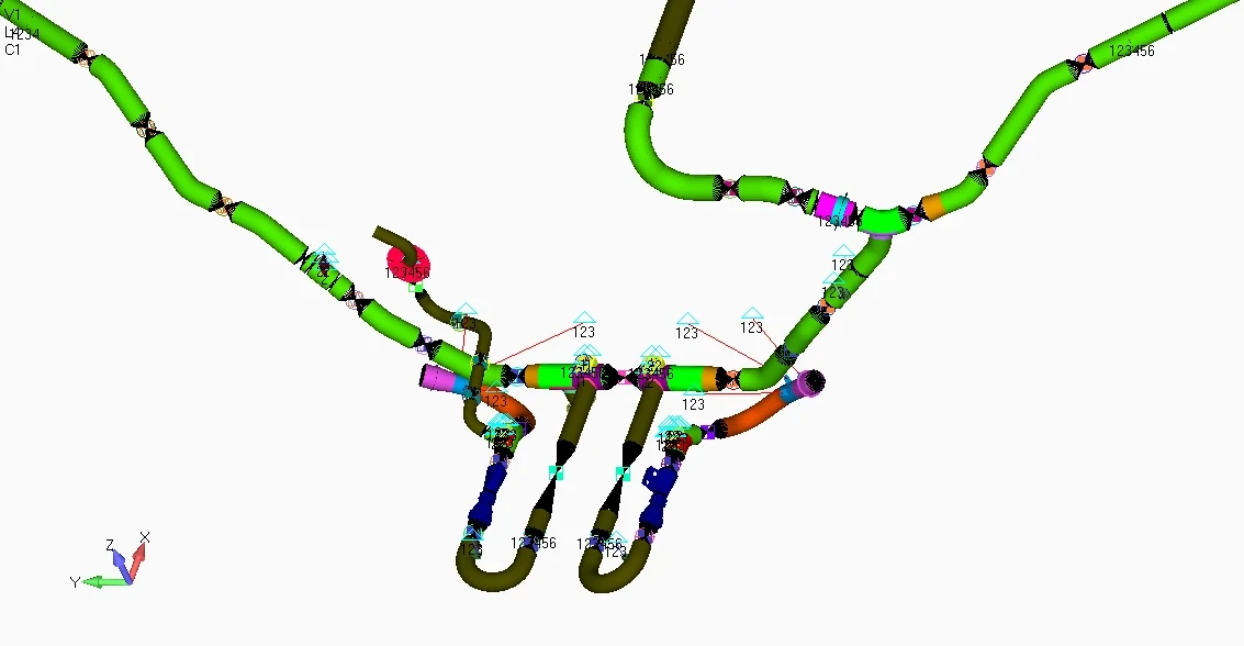
Forces and displacements of lines, expansion and ball joints and supports, with stresses compared with static and fatigue allowables, and the loads passed to the primary structure.
Leak and overheat detection
Compartment temperatures, detection times and detector setpoints, from a 0D model checked against CFD.
CFD of ducts and inlets
Duct breakage, pressure drop, ram air inlets and heat exchanger headers.
Certification documents
System description, safety assessment inputs, test proposals and test results as per FAR 25 or 23, and component qualification as per RTCA DO-160.
How a pneumatic system works and is certified
The pneumatic system, ATA 36
The pneumatic system, chapter ATA 100-36, supplies hot, high-pressure air to air conditioning, ice and rain protection, and pressurization systems. It can also serve seals, ejectors, drains, heating, radar pressurization, the on board oxygen generation system (OBOGS) and any other system that needs hot or pressurized air from the aircraft.
Its main aspects are distribution, flow, temperature and pressure. Distribution depends on the pressure drop of the subcomponents and on the control valves. Flow division, active or passive, determines how much flow each branch reaches.
On a commercial aircraft the system usually has shut-off and pressure regulation valves for the high and low stages of the engine compressor, a pre-cooler, and flow and pressure control valves for user systems such as air conditioning and ice protection.
Certification of pneumatic systems
Certification requirements and safety analyses such as the Functional Hazard Analysis, the Failure Mode and Effect Analysis (FMEA) and fault trees define the redundancy of the system. That is why aircraft have a system on the left and on the right side.
The system and its components can be certified by analysis, testing or similarity, as determined in a means of compliance (MOC) analysis. Tests usually include proof and burst pressure. If the ducts have moving joints, fatigue and accelerated life tests may be required.
The main certification reports are the system description, the safety analysis, the test proposal and the test results as per FAR 25 or 23, and the component qualification as per RTCA DO-160.
Analyses, indication and failures
The required analyses are usually pressure drop, distribution or flow sharing, thermal performance and temperature. Others cover the control of pressure, flow or temperature, that is, the dynamics of the plant and its control. CFD may also be required for duct breakage, pressure drop, ram air inlets and heat exchanger inlets (headers).
A very important subsystem is the indication and measurement of flow, pressure and temperature, and the fault detection, with dedicated sensors for each task. The indication is shown to the pilot with severity levels for flight safety. Failures can be over-temperature, over-pressure or unwanted leaks, which mainly affect the structure or electronic equipment.
Ducts, loads and structure
A system of hot, pressurized ducts that runs through a large part of the aircraft needs expansion joints or ball joints and supports attached to the primary structure. In operation, thermal expansion and pressure differences cause displacements, so the design needs the forces and displacements of the lines.
The forces generate stresses in bends, ducts and joints that are compared with static and fatigue allowables. A certification requirement is to know which loads the pneumatic system passes to the primary structure. The work needs a CAD tool and a structural FEA tool such as NX Nastran or Adina.
Tools, and where each one fits
Tools serve the engineering work. We say what each one does in the project.
| Tool | Role in the project | Status |
|---|---|---|
| CFD++ | Duct breakage, pressure drop, ram air inlets and heat exchanger headers, and thermal analyses of ducts and compartments. | Licensed |
| AMESim, FloMaster | Pneumatic network models: FloMaster for steady state and AMESim for transient and control. Run with the client’s license. | Client license |
| Femap, NX Nastran, Adina | Stress analysis of lines, joints and supports, and loads on the primary structure, including an FEA model delivered for the manufacturer’s use. | Licensed |
| MATLAB | Control and dynamics of the plant. Run with the client’s license. | Client license |
| Python, Nsp, Scilab | Control and dynamics tools that need no license and replace MATLAB when the client does not provide one. | In use |
| Excel/VBA | 0D model of all compartments: leak detection times, maximum compartment temperature and overheat detector setpoints. | Licensed |
Evidence you can check
Embraer project work.
Project work
| Project | What we did | Tools and tests | Result or venue |
|---|---|---|---|
| Embraer E2, 2014 to 2018: pneumatic system designProject | Design and analysis of the pneumatic system, design of the leak detection system, certification reports developed and reviewed. | Validated thermal model. Exclusive FEA model for the manufacturer. | Model used by the manufacturer. Reports used in the safety assessment. Complex decisions made without missing the deadline. |
| Embraer E2, 2014 to 2018: pneumatic system description (ATA 36)Project | System description certification report for the pneumatic system. | Supplier description reviewed. | Report issued by ATS. |
| Embraer E2, 2014 to 2018: components qualification (air management system)Project | Certification requirements cross-checked with each test proposal and result. | Valves, sensors, packs and computers. Questions and revisions requested from suppliers. | Process established and given to the customer: no part and no requirement or test left behind. Full-time engineer on site. |
| Embraer: pneumatic network model, AMESim and FloMasterProject | Steady-state and transient models. Pressure drop and temperature mapped in several operating conditions. | Laboratory pneumatic system plant, and aircraft system dynamics and control, modeled and validated. | Flow sharing and dynamic instability problems solved. |
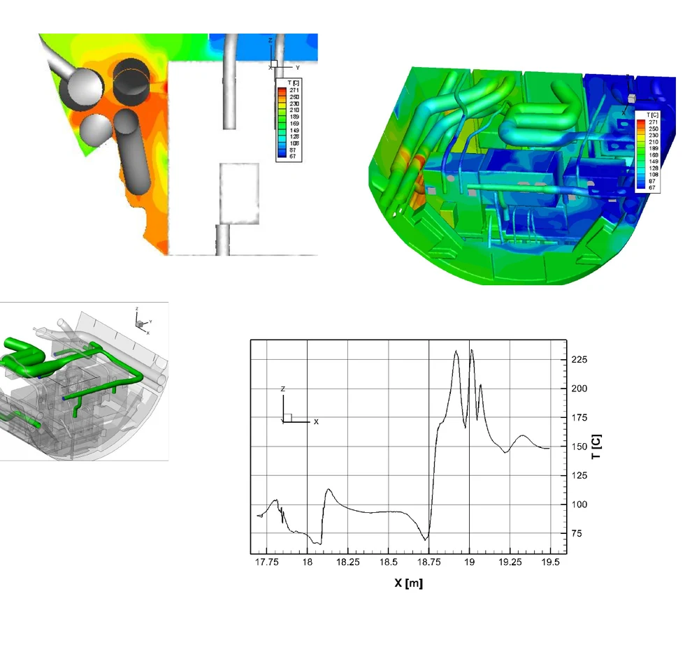
| Embraer: leak in a high-pressure duct (avionics)Project | Effect of the leak on the main temperature compartment and of the jets on the electronic boxes, and 3D detection time. | 3D CFD. | Leak effects studied for the design. |
| Embraer: compartment model, Excel/VBAProject | 0D model covering all compartments: detection times, maximum compartment temperature and overheat detector setpoint for each region. | Energy balance in each compartment. One compartment compared with a CFD result. | Detection times calculated. Setpoints defined for different regions. |
| Embraer: duct thermal CFD (pylon flange)Project | Insulation material and thickness for a pylon flange. | Thermal CFD. | Aluminum structure protected. |
| Embraer: overheat detector thermal CFDProject | Thermal analysis of the overheat detection system. | Thermal CFD. | Design approved with no false alarms due to conduction. Chance to optimize the detector support. |
| Embraer, 1997 to 2007: E190Industry | Focus on the pneumatic system, with work also on ECS and icing certification. | Industry experience of ATS’s founder at the manufacturer. | Work done at the manufacturer, before ATS. |
Examples
Select an image to see each example.

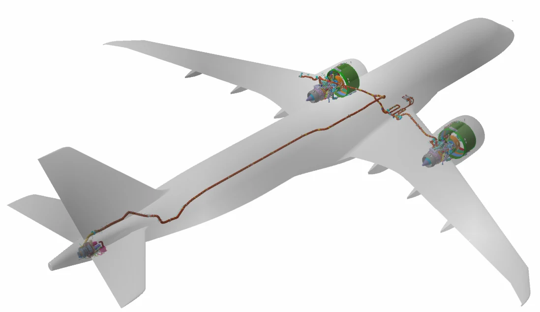
1 / 4
AMESim and FloMaster models
AMESim and FloMaster models of the pneumatic system: ducts, valves and control loops, for steady-state and transient analysis.
Request a technical proposalHow an engagement runs
Requirements and architecture
Certification basis, system requirements and the architecture of the pneumatic system.
Network model
Steady-state and transient models of pressure drop, temperature, flow sharing and control.
Detailed analysis
CFD of ducts and inlets, FEA of lines and supports, leak and detection analyses.
Tests and qualification
Test proposals, ground and flight tests, and component qualification against supplier tests.
Compliance with requirements
System description, safety assessment inputs and test reports issued by ATS, reviewed and submitted by you.
Start of operation
Operation support, service difficulties and follow-up.
Related services
Questions engineers ask before they hire us
Do you design the pneumatic system or only analyze it?
Both. In the Embraer E2 package, ATS did the design and analysis of the system, the design of the leak detection system and the certification reports. We can also join a design already under way and take only the analyses.
Which certification documents do you issue for a pneumatic system?
System description, safety assessment inputs, test proposals and test results as per FAR 25 or 23, and component qualification as per RTCA DO-160. You review them and submit them to the authority.
Do we need to provide a license for the tools?
For AMESim and FloMaster models, yes: the client gives access to its license for use in the project. MATLAB works the same way, and Python, Nsp and Scilab need no license and are alternatives to it. CFD++, Femap, NX Nastran, Adina and Excel/VBA are licensed by ATS.
How do you check the duct loads on the aircraft structure?
With a structural model of the lines, joints and supports in Femap with NX Nastran or Adina: forces and displacements from thermal expansion and pressure, stresses compared with static and fatigue allowables, and the loads passed to the primary structure, which is a certification requirement.
Can you work on site with our team?
Yes. On the component qualification of an air management system, an ATS engineer worked full time on site to keep the interface with suppliers smooth.
Is our data kept confidential?
Yes. We work under NDA, and your design data and reports stay with you.
Tell us about the system and the certification stage
Send the aircraft, the system and the question you need answered.
Email
aerospace@aerothermalsolutions.coPhone
+55 11 3854-4224OfficeAv. Pompéia, 634, cj. 107, São Paulo, SP, Brazil.
An ATS engineer replies. We work under NDA.