 Skip to content


Services / Pelletizing furnaces
Pelletizing furnace engineering: flow, temperature, erosion and emissions
Combustion chambers, burners, cooling zone, manifolds and expansion joints of pelletizing furnaces, studied in 3D with CFD++ and checked against plant data. Long-term work with Samarco on furnaces 1 to 4.
Long-term work for Samarco: furnaces 1, 2, 3 and the newest, 4. Combustion chamber, cooling zone, fan air manifold, flame deflection, refractory temperatures, erosion and particle deposition.
Pelletizing track record
- Samarco, furnaces 1 to 4Long-term work to understand the physical processes of its pellet furnaces.
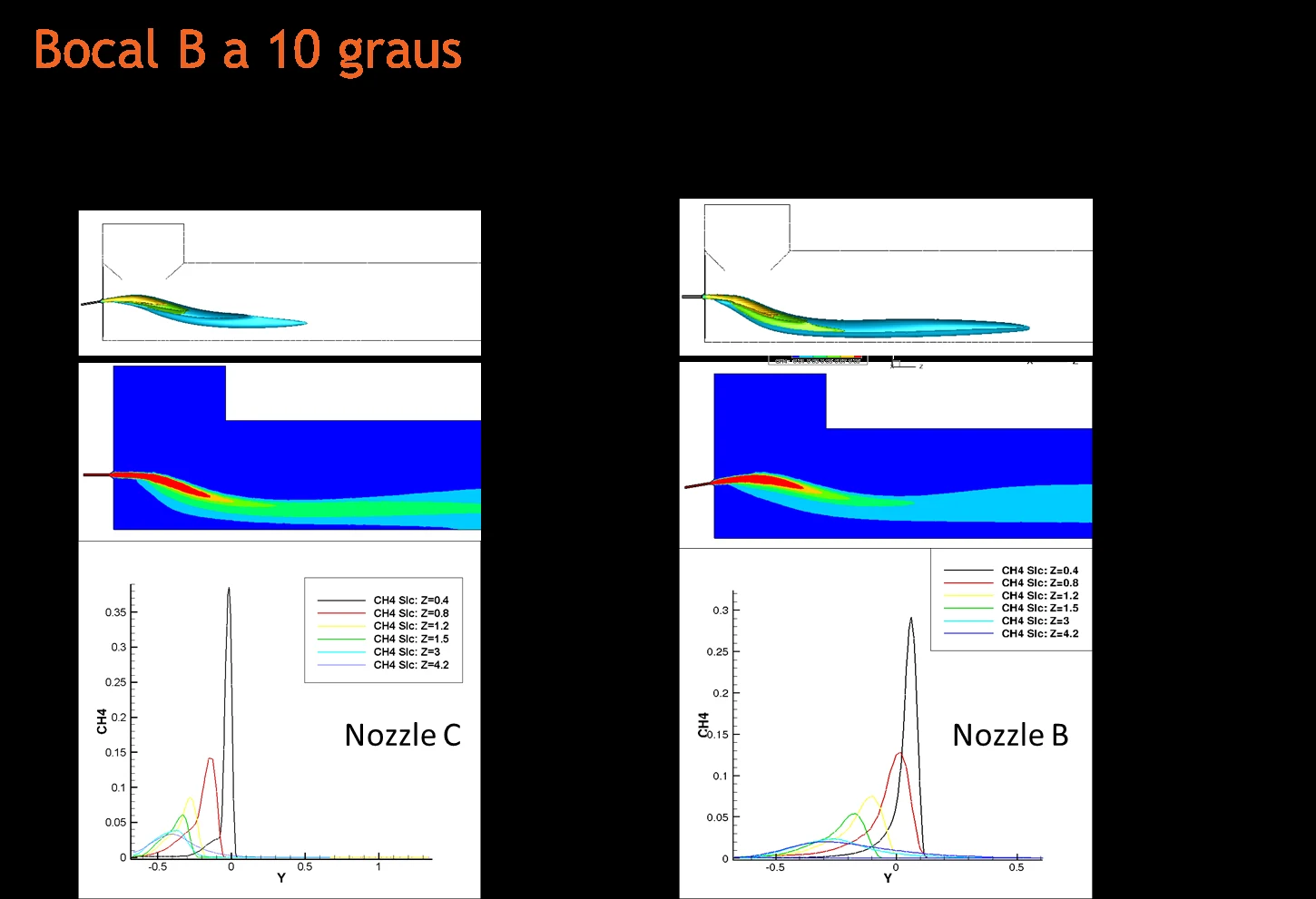
- Solution patented by the clientFlame deflection in the combustion chamber: six configurations simulated, lower maintenance cost, result validated by the client.
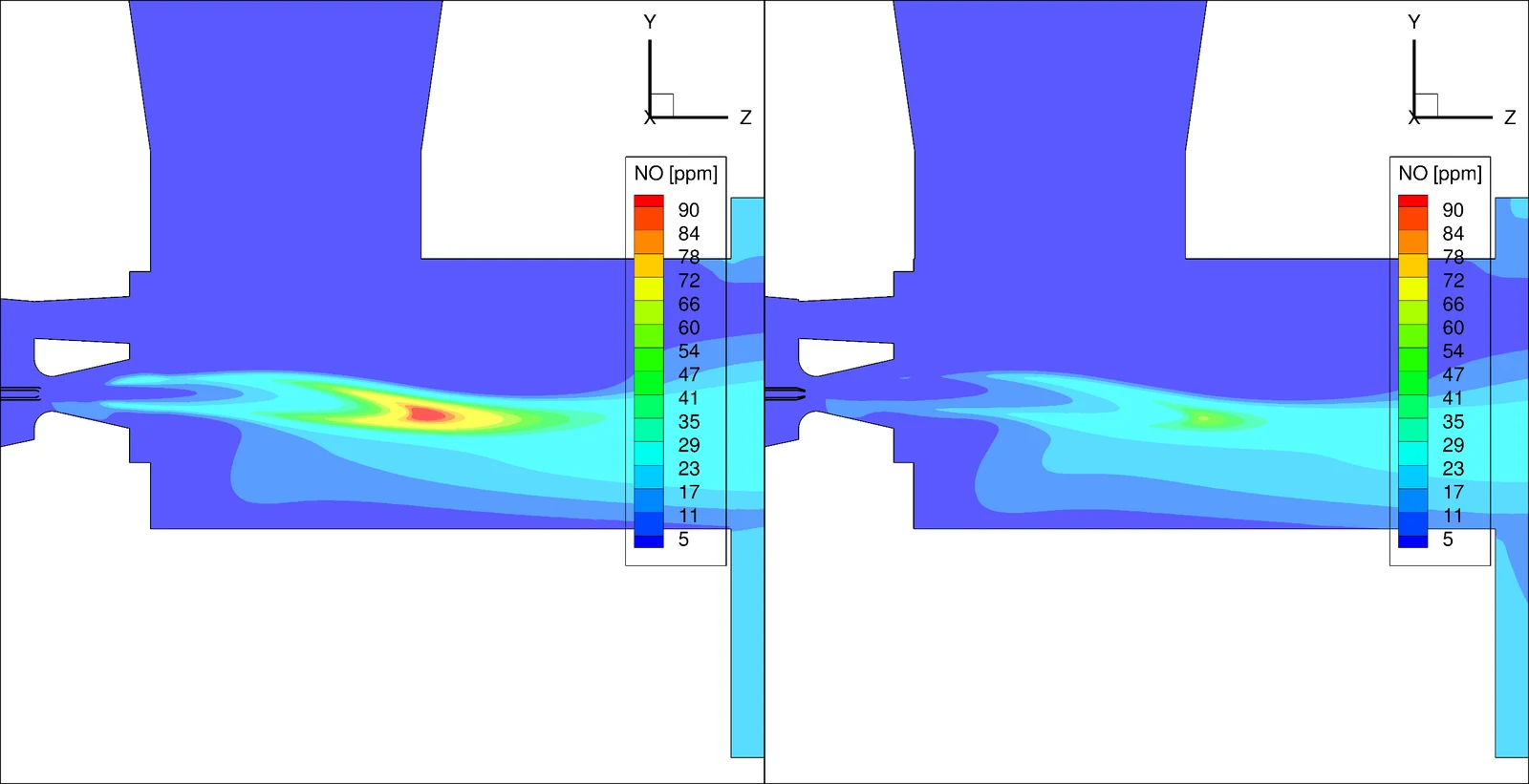
- Low NOx burnerMore than fifteen configurations studied before a single prototype, in a three-year R&D work.
- Refractory protectedWall temperatures compared with the limits of the bricks, and bricks redistributed along the furnace.
- Expansion jointsDeflectors that cut particle build-up, and a new joint design approved with CFD.
Complete solutions, from diagnosis to validation at the plant
We prefer whole projects to isolated simulations: ATS responsible for the analysis, the design of the solution, the test specification and the report.
The furnace as a whole
Burners, combustion chamber, cooling zone, air manifolds and joints studied together, because the quality of the pellet depends on temperature and on the time in each region.
One team across furnaces
The same engineers followed furnaces 1, 2, 3 and 4, so the learning from one furnace goes into the next.
Prototype and field test
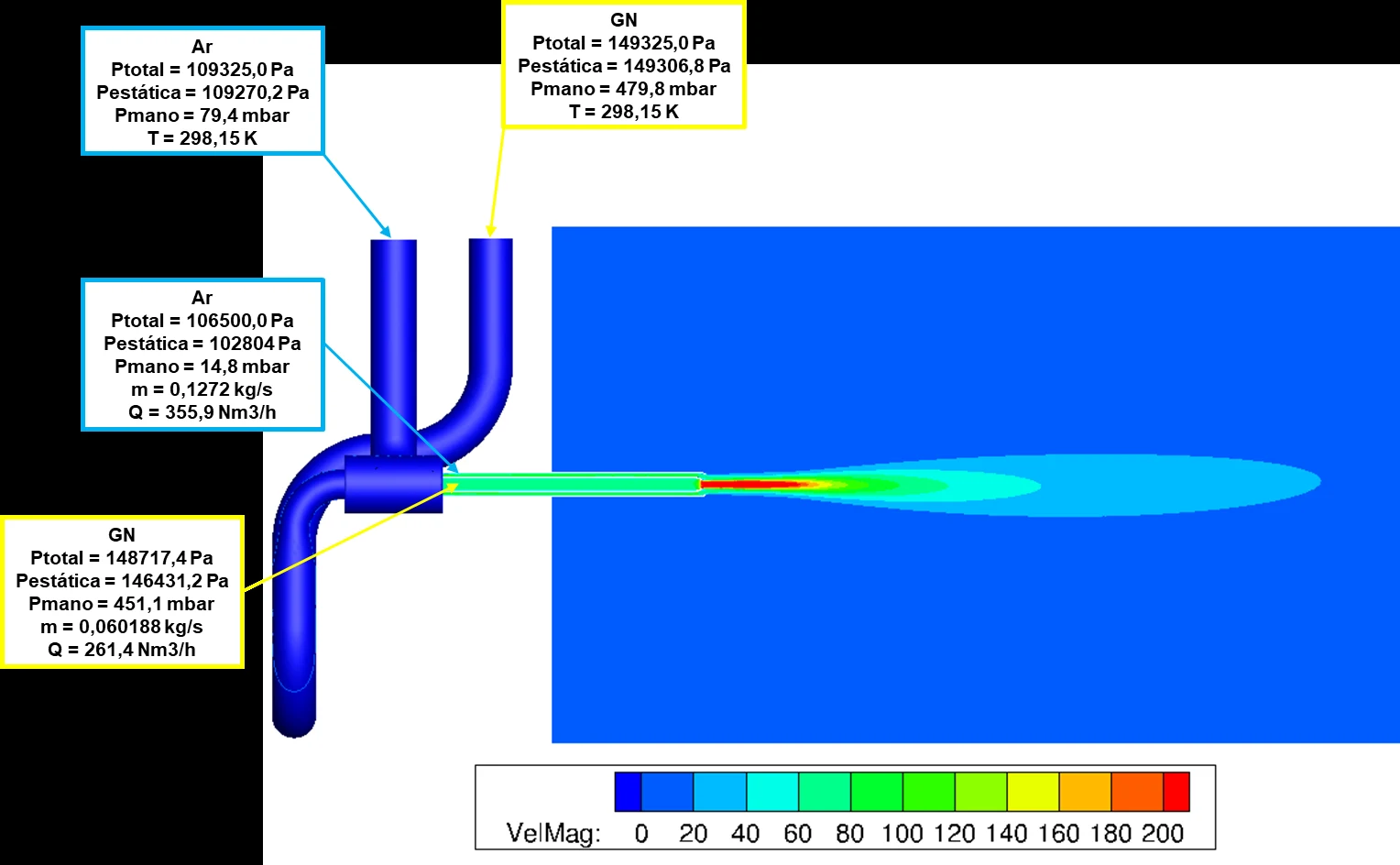
For burners, ATS specifies the prototype and the pressure, temperature and flow rig, and the result is checked in your furnace.
Need only a part? We define the scope with you.
What you receive
Combustion chamber and burners
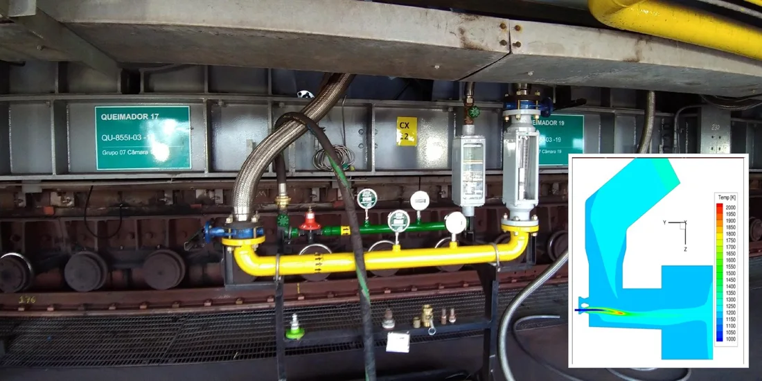
Flame position and deflection, and operating parameters to keep the flame away from the walls.
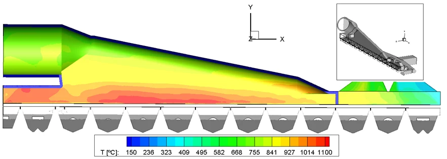
Temperature of walls and refractory
Wall temperature against the limit of each brick, and where to place each type of brick.
Cooling zone and air manifold
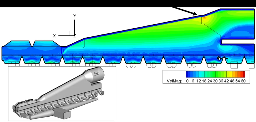
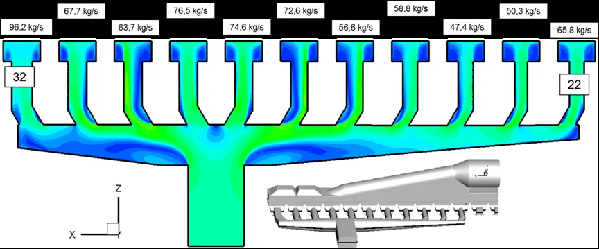
Flow rate and speed in each car, homogeneity of the pellet bed and flow distribution of the air manifold.
Erosion and particle deposition
Places most exposed to air erosion by iron oxide particles, and deposition in expansion joints and bends.
Ash on the grate car
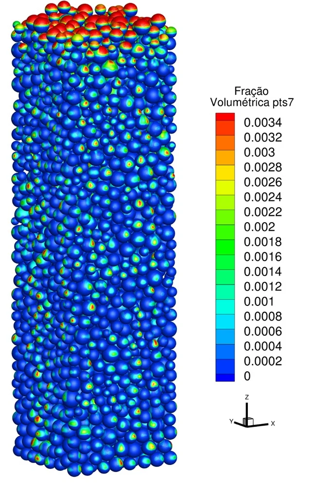
Pellet bed stacked by DEM (LIGGGHTS) and CFD of the air and charcoal ash through the voids, with heat transfer to the pellets, to find where the ash builds up.
Emissions
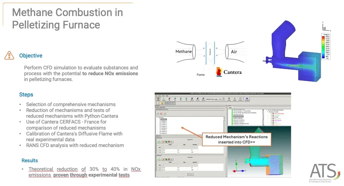
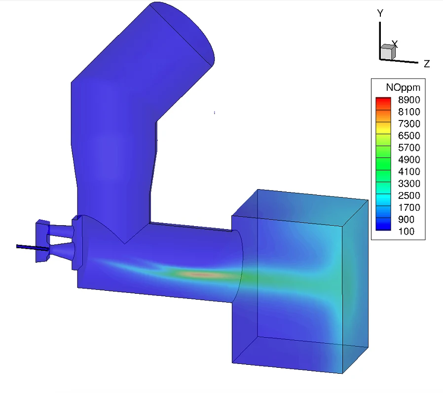
NOx, CO, CO2 and SOx of burners and pellets, with chemical kinetics (Cantera) reduced for CFD. Details on the burner page.
How a pelletizing furnace works
The process
Pelletizing turns iron ore fines into spherical pellets. They are formed by agglomeration and gain mechanical strength after firing and sintering at high temperature in ovens.
These linear furnaces are very long and have more than 40 natural gas or liquid fuel burners. Pellets feed blast furnaces for steel, or direct reduction systems for iron. In the blast furnace the stack of pellets must let air circulate and carry the weight of the upper layers.
Regions and quality
The furnace has drying, pre-burning, burning, post-burning and cooling regions. The duration of each step, set by the speed of the grate cars, and the temperature the pellets are submitted to strongly influence pellet quality.
That is why the combustion process and the temperatures along the furnace, and their distribution inside each car, are worth studying.
Emissions and efficiency
The CO, CO2, NOx and SOx produced by burning fuels and pellets are also of interest. Companies want to reduce their environmental footprint and operate within the limits of the legislation, so they study different fuels and different burners.
Generally, the improvement in emissions comes with higher efficiency in parts of the process. It is a chance to rethink the equipment and the burner design.
A digital model of the plant
ATS uses CFD++ to reduce the cost of prototype tests and fabrication, because it can build an accurate digital model of the combustion process of the plant.
Tools, and where each one fits
Tools serve the engineering work. We say what each one does in the project.
| Tool | Role in the project | Status |
|---|---|---|
| CFD++ | Fluid flow, heat transfer, combustion and particles in 3D. ATS is the exclusive CFD++ representative in Brazil. | Licensed |
| Tecplot 360 EX | Post-processing and automation macros, including erosion rate calculation. | Licensed |
| Cantera | Chemical kinetics, with mechanisms reduced for CFD. | In use |
| LIGGGHTS | Discrete element method (DEM) to stack particle beds, such as the pellet bed on the grate car, later used in the CFD. An open-source version, LIGGGHTS-PUBLIC (GPL, based on LAMMPS), is available. | Per project |
| Femap, NX Nastran, Adina | Stress analysis, contact, hyperelastic and nonlinear materials, thermal and fluid-structure coupling. | Licensed |
| iChrome Nexus | Optimizer and manager of complex CAD, CFD and FEA workflows. | Licensed |
Evidence you can check
Work for mining companies in Brazil.
Project work
| Project | What we did | Tools and tests | Result or venue |
|---|---|---|---|
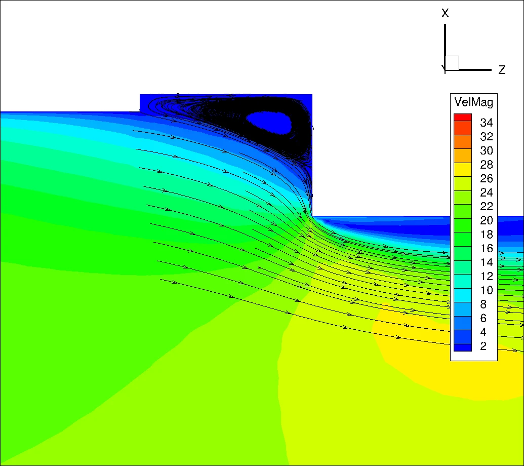
| Samarco: flame deflectionProject | Deflection of the natural gas jet in the combustion chamber, which deposited molten material and raised maintenance. | 3D CFD++. Six configurations simulated. | Higher momentum flow and a new inclination angle. Lower maintenance cost. Solution patented by the client, who implemented it and validated the results. |
| Samarco: flame deflection, furnace 4Project | Burner parameters adjusted to reposition the flame and avoid erosion of the lower part of the combustion chamber. Continuation of the work on furnace 3. | 3D CFD++, all burner gas flow configurations. | New burner inclinations and position reduced the CH4 at the lower wall and the flame deflection. |
| Samarco: refractory temperaturesProject | Refractory bricks eroding and breaking with temperature, and a pellet bed with poor cooling air distribution. | 3D CFD++ of the cooling zone, the manifold and the cars. | Wall temperature compared with the limits of the bricks. Bricks redistributed along the furnace. Places most exposed to erosion by FeO particles located. |
| Samarco: expansion jointsProject | Particle deposition in expansion joints of hot air ducts carrying iron oxide particles, and a new joint design from a partner engineering firm. | 3D CFD++ with particles. | Deflector devices that cut particle build-up. Efficiency of each solution quantified. New joint design approved. |
| Vale: ash on the grate carProject | Structural damage in parts of the furnace from charcoal ash released in the pelletizing process. | Pellet bed generated by DEM (LIGGGHTS), mesh in Ennova and MIME, and CFD of the air and ash through the voids of the bed, with heat transfer to the pellets. | Region of ash accumulation inside the furnace identified and confirmed. |
| Samarco: Low NOx burnerProject | New burner for the gas burners of the pelletizing furnace. More than fifteen configurations studied before the prototype. | CFD++ with chemical kinetics and thermal NOx. Pressure, temperature and flow rig specified by ATS. Three-year R&D. | NOx reduction target reached at the same production rate. One prototype. See the burner page. |
Examples
Select an image to see each example.
How an engagement runs
Diagnosis and goal
We define the problem, the operating conditions and the target with your team.
Model
The geometry of the equipment is prepared and the physics that apply are chosen.
Analysis
Numerical calculation based on the applicable physical principles.
Checks and validation
Results are checked for consistency and compared with tests, plant data or the literature.
Solution and report
Design of the solution, specification of the test when needed, and the report.
Follow-up
Support in the field test or in operation, and revisions.
Related services
Questions engineers ask before they hire us
Which parts of the furnace do you study?
Combustion chamber, burners, cooling zone, fan air manifold, grate cars, expansion joints and air ducts. We can take the whole furnace or a single problem.
Do you check the results at the plant?
Yes. The burner work includes the specification of a prototype and of a measurement rig, tested in the client’s furnace.
Can you help with maintenance problems?
Yes. In flame deflection, the new configuration lowered maintenance cost, and the client patented the solution.
Is our data kept confidential?
Yes. We work under NDA, and your design data and reports stay with you.
Tell us about the furnace and the problem
Send the furnace, the operating conditions and the question you need answered.
Email
sales@aerothermalsolutions.coPhone
+55 11 3854-4224OfficeAv. Pompéia, 634, cj. 107, São Paulo, SP, Brazil.
An ATS engineer replies. We work under NDA.