 Skip to content


Services / Icing and aircraft systems / Ice protection systems
Ice protection systems engineering: design, testing, simulation and certification
ATS is an engineering company: we design, test and certify the anti-ice and de-ice systems of your aircraft and its air data probes, and issue the certification documents, ready for you to review and submit to the authorities. We size the heaters with thermal analyses validated in icing-tunnel tests, covering water collection, the water film and heat conducted through the skin. The method, developed at USP and used at Embraer, has been kept current with client projects on different aircraft and the new icing requirements.
See the requirements
- FAR 25 Appendix O: supercooled large drops (SLD)
- FAR 33 Appendix D and EASA CS-25 Appendix P: ice crystals and mixed phase
- ASTM F3120: general aviation
- SAE AS5562 and FAA TSO-C16b: air data probes
- EASA Special Condition VTOL and EUROCAE ED-314: icing on eVTOL
Led by Dr. Guilherme A. Lima da Silva: anti-ice design and certification of wings, pitot, TAT, static port and smart probes at Embraer (1997 to 2007), with tests in the NASA icing tunnel. His 2007 Journal of Aircraft papers on airfoil anti-ice simulation remain his most cited.
Not enough power. Over part of the heater the power cannot keep the surface above 0 °C and ice forms on the protected area.
Running wet. The surface stays above 0 °C but not all water evaporates: it runs off the heater and refreezes as a spanwise ridge. More extent reduces the ridge only a little and moves it aft, at a high cost in total power; power density is what reduces it most.
Fully evaporative. All collected water evaporates on the heater and there is no ridge. It needs much more power than running wet.
Main assumptions
- SAE AIR1168/4 Example 9.2 equation, applied point by point on a 1 m chord leading edge (1.58 % c radius) at 4° angle of attack, with stagnation slightly on the lower surface.
- Fixed condition: 250 KTAS, sea level, −17.8 °C, 0.50 g/m³, 20 µm MVD (FAR 25 App. C intermittent maximum).
- Heated surface held at 4.4 °C with 100 % efficiency; outside the heater water freezes at the highest rate the balance allows; 10 min exposure.
Simplified engineering model, not a simulation. References: SAE AIR1168/4, Ex. 9.2; Jeck, DOT/FAA/AR-00/30, 2002 (FAR 25 App. C); Bragg, Broeren & Blumenthal, 2005.
Want to run the numbers for your case? The SAE AIR1168/4 spreadsheet, with Examples 9.1 and 9.2 in English and Portuguese, is sent by e-mail.
Request the spreadsheetParameters and solved variables
Icing condition (SAE AIR1168/4 Example 9.2)
- Airspeed / altitude
- 250 KTAS / sea level
- Air temperature
- −17.8 °C (0 °F)
- LWC / MVD
- 0.50 g/m³ / 20 µm
- FAR 25 App. C envelope
- Intermittent max. (above continuous)
- Running-wet surface
- 4.4 °C (40 °F)
- Chord / exposure
- 1 m / 10 min
- Angle of attack / leading-edge radius
- 4° / 1.58 % c
Solved variables
- Recovery temperature
- —
- Stagnation h (Frössling)
- —
- Water catch at stagnation
- —
- Running-wet requirement at leading edge
- —
- Total heater power
- —
- Water leaving the heater
- —
- Ice mass outside the heater
- —
- Highest ridge
- —
How it is calculated
It is the SAE AIR1168/4 Example 9.2 equation (running wet, Fig. 3F-18): q = h(Ts − Trec) + ṁ·cw(Ts − T∞) + evaporation (Chilton-Colburn analogy, saturated air). With the example’s ṁ and h it gives 5.90 W/in², against 5.9 in the document. Here it is applied point by point on a 1 m chord leading edge at 4° angle of attack, marching the water film from stagnation; outside the heater the water freezes at the highest rate the balance allows and forms the spanwise ridge (Bragg et al., 2005). The condition is above the continuous maximum and inside the intermittent maximum of FAR 25 Appendix C (DOT/FAA/AR-00/30). 100 % heating efficiency, as in Fig. 3F-18; AIR1168/4 recommends 70 % at the heater edges.
Ice protection systems track record
- IndustryEmbraer, 1997 to 2007: anti-ice design and certification for the wing and for pitot, TAT, static port and smart probesSlat and wing thermal anti-ice with LEWICE and the NASA icing tunnel. Smart probes certified with CFD++, ahead of TSO-C16b.
- IndustryEngine anti-ice system developed with tests and simulationSAE technical paper, 2007, with the Embraer team.
- ProjectTurkish Aerospace STC on a surveillance aircraft: ice-protection substantiation and certification-support analyses (FENSAP based)Four-year program, in partnership with Akaer. ATS performed the substantiation and certification-support analyses; the STC and certification were held by Turkish Aerospace and Akaer.
- ProjectJoby eVTOL and an LWC probe redesign: heat load, water catch and optimum heater powerAir data probe for cruise during icing escape, and an electrically heated LWC probe validated in an icing tunnel.
- Certification and standardsAir data probe power density model, SAE AC-9C Portland, 2010Compared FAR 25, EASA, BS 2G 135 and SAE AS5562 conditions.
- iceAccretionFoamOur 3D solver iceAccretionFoam will add thermal protection in Phase 2FAPESP PIPE, 2027/28. Product development, separate from the project experience above.
Complete packages, from design to certification reports
We prefer whole, long-term programs to isolated runs: ATS responsible for the ice protection system design, the tests and the certification evidence.
What a package covers
Ice protection system design, sizing and integration; test planning and execution in the icing tunnel, on the ground and in flight; and the certification documents, ready for submission to the authority. We issue them ourselves, whether from analysis or test results: system description, safety assessment, certification plan, reports or any other document the program needs. You review them and submit them to the authorities. This is our differentiator.
One team for the whole program
The same engineers carry the program from the first analysis to the last report, so design decisions, test points and evidence stay consistent over the years. Simulation runs inside this work, it is not the product.
An example: Akaer, ASOJ TA
2020 to 2024. An STC of Turkish Aerospace (TA) for a surveillance aircraft, in partnership with Akaer: ATS performed the ice-protection substantiation and certification-support analyses, with simulation and test support.
How a project happens
A program runs through five certification reports: system description; safety assessment; certification plan; icing-tunnel and flight test planning and results; and numerical model description, validation and results.
Need only a part? We define the scope with you.
Anti-ice and de-ice, and where the ice goes
The two families behave differently, so the analysis and the evidence differ.
| Anti-ice | De-ice | |
|---|---|---|
| Purpose | Prevent ice from forming on the protected surface. | Let ice form, then melt or expel it. |
| Operation | Steady state, on during the icing encounter. | Transient, in cycles of accretion and shedding. |
| Water | Residual water forms and can run back and refreeze aft of the protected area. | Melt water and shed ice pieces. |
| What we analyze | Surface temperature, wet and dry limits, runback and refreeze location, power density and margin. | Cycle timing, ice thickness at activation, residual ice and where shed pieces go. |
| Typical hardware | Hot air from bleed, electrothermal heaters. | Pneumatic boots, electrothermal cycles, electro-expulsive systems. |
Thermal systems are the most common on commercial aircraft. New systems may use hydrophobic surfaces or electro-expulsive de-ice, and we model those as well as mechanical protection.
Ice protection systems are an integration problem
It touches other systems
The ice protection system connects to pneumatic, electric, indication, navigation and stall protection systems.
It must not interfere
Its operation cannot degrade those systems, and they must be evaluated under icing conditions.
It needs operating rules
Flying in icing conditions requires specific maintenance and operation procedures.
The IPS has multiple interfaces with aircraft systems and requires specific procedures for operation.
Dr. Guilherme A. Lima da Silva, The Icing Engineering Process
The physics we solve
Five layers from the free stream to the skin, solved together.
- 1Free stream flowSpeed, altitude and angle of attack from the mission.
- 2Gaseous flow with dropletsAir and water vapor mixture. Droplet trajectories and impingement.
- 3Momentum and thermal boundary layersIntegral or differential solution, or CFD with heat transfer, with laminar-turbulent transition and streamwise gradients.
- 4Water filmBeads, film and rivulets. Evaporation, energy balance and runback.
- 5Solid surfaceConduction through skin, heater and structure layers.
Effects that decide the answer
Laminar-turbulent transition, streamwise temperature and pressure gradients, and the hydrodynamics of runback water all change temperature and evaporation, so they are in the model.
What you receive
Surface temperature, water mass flow, wetness, runback limits, power density and margin, and the residual ice left when the system fails or is off.
One CFD tool for all five layers
All of this physics can be solved inside a single CFD tool, such as iceAccretionFoam, CFD++ or FENSAP-ICE. It is separated into layers here only for clarity.
Where the model comes from, and how it evolved
From the PhD at Poli-USP to iceAccretionFoam, with the papers behind each step.
The thermal balance couples the skin, the water film and the air: conduction along the wall, heat exchange with the water, droplet enthalpy and kinetic energy, and evaporation. It was born at Embraer and Poli-USP and is still being developed at ATS.
- 2003–2009Research
Poli-USP, supported by Embraer and FAPESP: anti-ice model with continuous film and rivulets (runback).
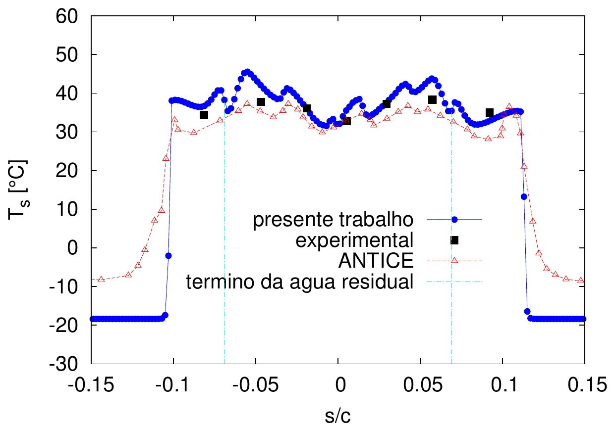
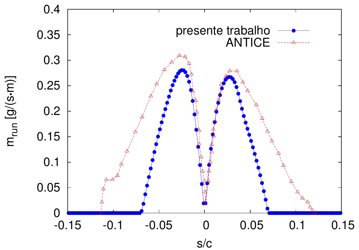
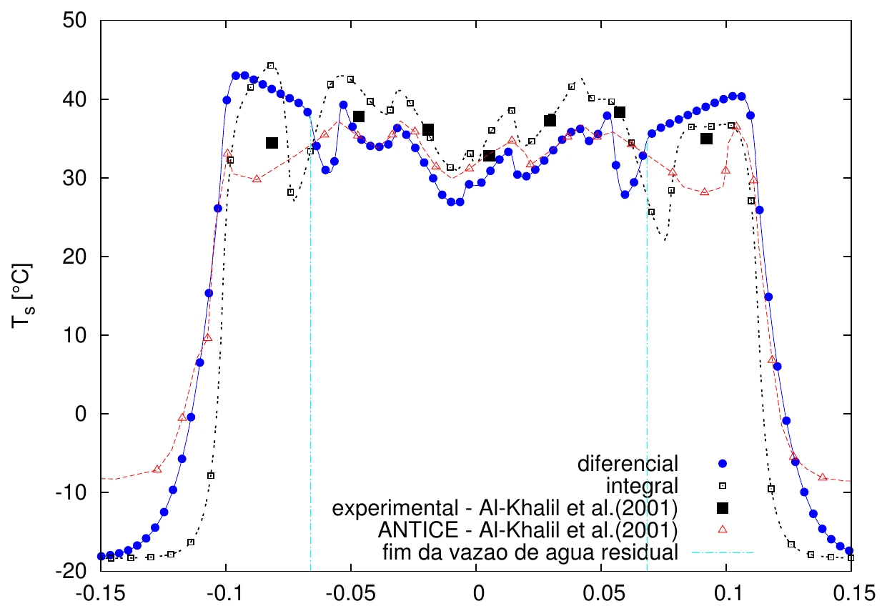
Validated against the Al-Khalil et al. (2001) test and NASA ANTICE. MSc (2003) and PhD: thesis at Poli-USP.
- 2007–2010Research
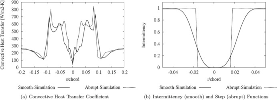
Laminar-turbulent transition and intermittency in heat transfer and ice shape.
Stefanini, Silvares, Silva and Zerbini (COBEM 2007; AIAA 2008-474). See Publications.
- 2008–2009Research
Cal State Long Beach: Cebeci compressible differential boundary layer integrated into the code.
Silva, Silvares, Zerbini, Hefazi, Chen and Kaups, AIAA, 2009.
- 2010–todayProject
Pitot probes: heat load and test envelope models, from spreadsheet to Python.
Presented at SAE AC-9C (Portland, 2010) and used in eVTOL programs and probe certification.
- 2011Research
Wall functions for heat transfer on rough surfaces.
Silva, Arima, Branco and Pimenta, SAE 2011-38-0023.
- ProjectsProject
Electrothermal anti-ice code to define the power distribution in probes.
LWC probe: CFD for Cp and impingement, optimum electric power distribution and icing tunnel validation.
- 2023iceAccretionFoam
Start of the collaboration with Prof. Hrvoje Jasak.
Starting point of iceAccretionFoam, our own 3D solver (NUMAP-FOAM Summer School 2023).
- 2024iceAccretionFoam
First iceAccretionFoam paper and glaze ice at SAE AC-9C.
Teixeira da Silva et al., ICAS 2024-1112, Florence; SAE AC-9C, Ottawa.
- 2025iceAccretionFoam
Two papers in Philosophical Transactions of the Royal Society A, with Prof. Jasak.
Impingement and rime ice and glaze ice; presentation at SAE AC-9C, CIRA, Capua.
- 2026iceAccretionFoam
FAPESP PIPE 2025/19697-9 and the ATS accretion model in the site applets.
Phase 1 (July 2026 to February 2027): 2D beta, rime and glaze; Phase 2: 3D MVP with thermal anti-ice and de-ice (FAPESP, post). The ATS accretion model in Python, checked against LEWINT and the NASA test, runs the icing applets on the site.
Tools, and how mature each one is
We say what runs today and what is still in development, so you can plan the evidence.
| Tool | Role in ice protection systems work | Status |
|---|---|---|
| ATS thermal codesATS, 2D | Integral (Ambrok and superposition) and differential boundary-layer methods coupled to a water film with beads, film and rivulets. Compared with the NASA anti-ice experiment of Al-Khalil et al. (2001). | In use |
| CFD++Metacomp | CFD with heat transfer: external flow, droplets and thermal balance on the wall, plus internal hot-air flow when the system needs it. | In production use |
| LEWINT (LEWICE)NASA, American Kestrel | Fast thermal analysis of anti-ice and de-ice heat balance. ATS holds a LewInt licence. | Licensed |
| FENSAP-ICEAnsys | Ice protection systems module on a licence you provide, as on the Akaer STC ice protection systems work where the customer required it, compared with the other tools when a cross-check helps. | Client-supplied licence |
| iceAccretionFoamATS, foam-extend 5.0 | Finite-area water film exchanging heat with the wall, and 2D shell conduction for electrothermal heaters, in the same 3D solver that grows the ice. | Phase 2 target, 2027/28 |
Air data probe envelope mapping
Makers of pitot, TAT and smart probes, angle-of-attack vanes and ice detectors are a large market, with hundreds of suppliers in the US alone, and their certification depends on conditions that differ from standard to standard. We map them.
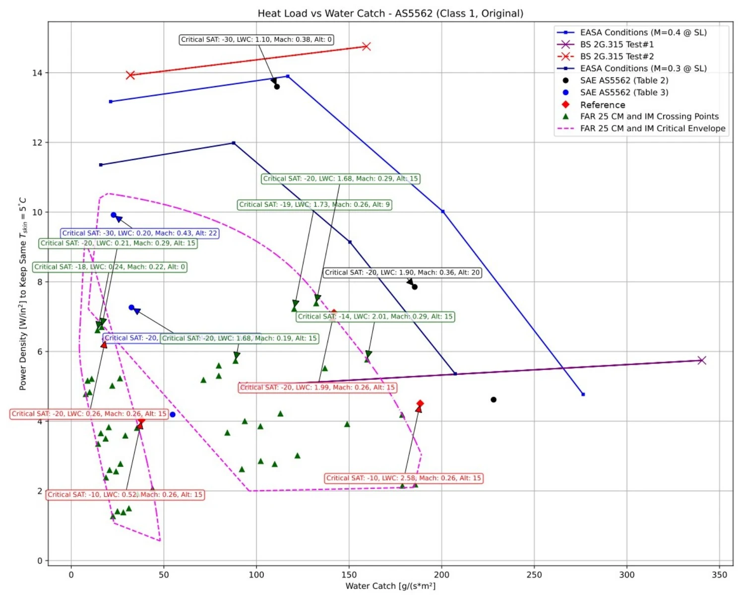
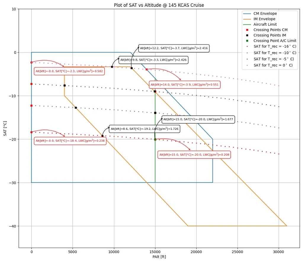
What the mapping does
Python programs place the operating points of your aircraft and the icing tunnel test points on the same heat load against water catch plane as the old and current standards: FAR 25 Appendix C, EASA, BS 2G 135 and SAE AS5562, which FAA TSO-C16b calls. You see which conditions drive the heater power and which tests are worth running. The method started as a spreadsheet model presented at SAE AC-9C in Portland, with a lumped heat and mass balance, ice crystal and water catch terms and CFD++ collection efficiency (presentation). It now runs as Python programs.
Why probes have their own standard
Pitot probes are qualified by TSO-C16b, which calls SAE AS5562, and by ETSO-C16, not only by FAR 25 Appendix C or O. On Air France flight 447, in 2009, ice crystals blocked the pitot probes and started the chain of events, according to the French BEA final report.
CFD on the real aircraft
CFD gives the water catch, and the LWC concentration and speed near the probe, and maps the heat load on the heater. We did this for an eVTOL air data probe that had to be certified for cruise during the escape from icing conditions.
Pitot probe standards and our certification
Pitot probe qualification moved from a 1948 airspeed tube specification to the ice and rain conditions of SAE AS5562, which FAA TSO-C16b calls since 2017. The E170/190 smart probe certification at Embraer, led by Dr. Guilherme, answered an EASA CRI in 2003 and 2004, before the FAA and EASA standards reached those liquid water conditions. Select a milestone to read the detail.
- Dec 1947
SAE AS393, the first pitot heater standard
SAE AS393, Airspeed Tubes, Electrically Heated. Revised in 1960 and declared noncurrent in 2002.
- 1 Sep 1948
FAA (then CAA) TSO-C16, first edition
FAA (then CAA) TSO-C16, Airspeed Tubes (Electrically Heated), first edition, with the performance requirements of SAE AS393. Record: FAA TSO-C16, Accuris
- 1967
British Standard BS 2G 135 with supercooled water tests
British Standard BS 2G 135, Electrically-Heated Pitot and Pitot-Static Pressure Heads (Amendment 1 of 1973), with the supercooled water tests of section 8.7.
- 24 Oct 2003
EASA ETSO-C16, based on SAE AS393
EASA ETSO-C16, based on SAE AS393. Document: EASA ETSO-C16
- 2003–2004
Embraer E170/190 smart probes: EASA CRI answered
Embraer, E170/190: the EASA CRI for the smart probes is answered with the AS5562 liquid water conditions, more than a decade before TSO-C16b, using simulation and CFD++. The E170 was validated by EASA on 20 February 2004 (EASA type certificate data sheet).
- 6 Oct 2006
FAA TSO-C16a adds the icing tests and BS 2G 135
FAA TSO-C16a: moves from SAE AS393 to SAE AS8006 (1988) and adds the icing test of 14 CFR 25 Appendix C intermittent maximum, plus the BS 2G 135 supercooled water tests 1 and 2 of paragraph 8.7.2.
- 14 Oct 2009
EASA ETSO-C16a, harmonised with the FAA
EASA ETSO-C16a (ED Decision 2009/014/R), harmonised with FAA TSO-C16a after the Air France 447 accident, with the same BS 2G 135 icing test, section 8.7. Documents: EASA ETSO-C16a, EASA terms of reference
- Feb 2016
EUROCAE ED-225, the counterpart of SAE AS5562
EUROCAE ED-225, with the same title and scope as SAE AS5562: ice and rain minimum qualification standards for pitot and pitot-static probes.
- 27 Jan 2017
FAA TSO-C16b calls SAE AS5562
FAA TSO-C16b: calls SAE AS8006A and SAE AS5562, in place of the British Standard. Document: FAA DRS, TSO-C16b
- 21 Feb 2018
EASA ETSO-C16b, based on the FAA TSO-C16b
EASA ETSO-C16b (ED Decision 2018/002/R), based on FAA TSO-C16b. Document: EASA ETSO-C16b
Evidence you can check
Client and Embraer project work, and the papers behind the method.
Project work
| Project | What we did | Tools and tests | Result or venue |
|---|---|---|---|
| Akaer STC, surveillance aircraftProject | Ice-protection substantiation and certification-support analyses, with simulation and test support, inside a four-year STC program for Turkish Aerospace (TA), in partnership with Akaer. | FENSAP-ICE, as the customer required. | Certification reports ready for submission. 2020 to 2024. |
| Joby (eVTOL) air data probeProject | Heat load mapping on the probe for cruise during escape from icing conditions. | 3D CFD water catch, LWC concentration and speed near the probes. | Python programs for operating and tunnel test points against SAE AS5562, and certification support. 2023 to 2024. |
| LWC probe redesign, Droplet Measurement TechnologiesProject | CFD and ice protection system analysis for the best electrical heating design of an LWC probe. | CFD for Cp and impingement, electrical anti-ice code, icing tunnel tests to validate the code. | Optimum heating power distribution on the probe. |
| Zodiac Aerotechnic: ice detector shapeProject | Shape optimization of an ice detector to weaken the shock wave and increase convective heat transfer, so the heater works better. | CFD on several candidate shapes. | Best heat transfer coefficient selected, drag minimized, shock wave weakened. |
| Embraer: smart probes certificationIndustry | Certification of the E170/190 smart probes. The response to an EASA CRI anticipated, in 2003/2004, the liquid water conditions of SAE AS5562, which TSO-C16b only included more than a decade later. | Innovative approach with intensive use of simulation and CFD++. | E170/190 programs, 2003 to 2004. |
| Embraer: wing (slat and wing anti-ice)Industry | Design and certification of the thermal anti-ice of the slat and wing, and of the pitot, TAT and static port probes. | LEWICE simulation and tests in the NASA icing tunnel. | 1997 to 2007. |
| Embraer: engine anti-iceIndustry | Engine anti-ice protection system developed with experimental and numerical approaches. | Tests and simulation. | SAE technical paper, 2007. |
| Pitot tube, A-4 Skyhawk, Brazilian NavyProject | Water collection on the pitot tube. The distribution feeds 1D or 2D heater models. | CFD++. | Peak β of 0.916. |
| Air data probes: heat load and envelope analysisProject | Python programs that define the operating points and the icing tunnel test points, compared with old and current standards: FAR 25 Appendix C, EASA, BS 2G 135 and SAE AS5562, which FAA TSO-C16b calls. | Python programs: heat load against water catch and operating points. | Used at Joby and presented at SAE AC-9C. |
| Icing tunnel and pitot tests at UFRJProject | Design and installation of the first icing tunnel in Brazil, pitot icing tests in flight and in the tunnel, and the investigation of the Air France 447 accident. | Icing tunnel, flight tests and thermal models. | J. Braz. Soc. Mech. Sci. Eng., 2016. |
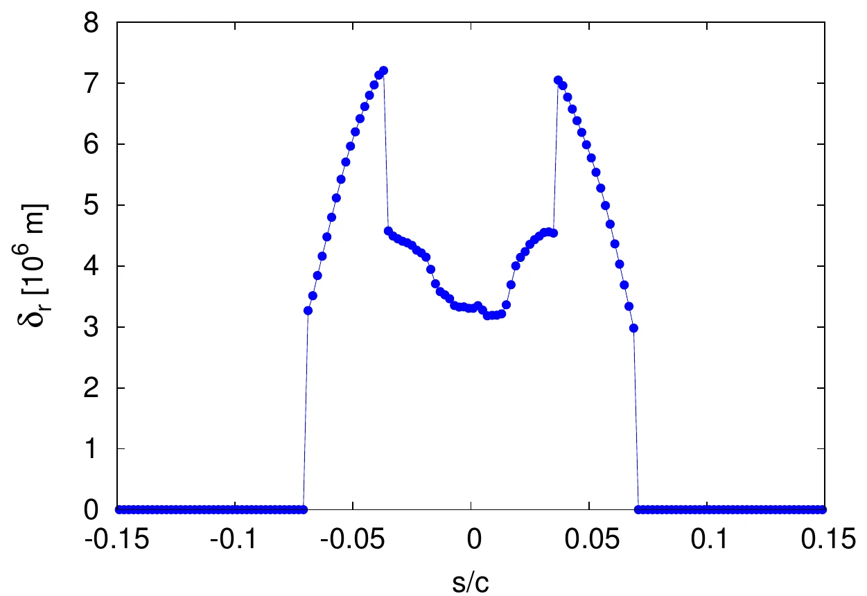
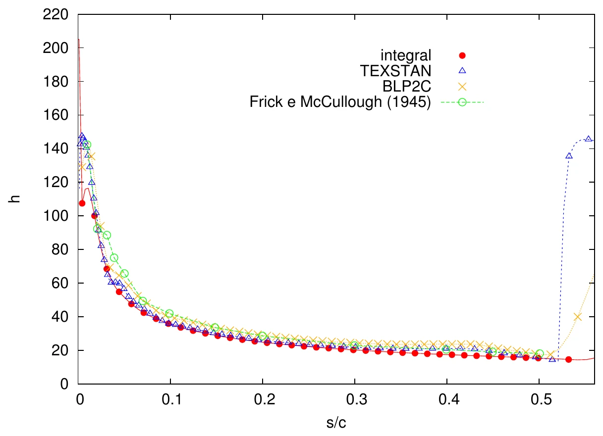
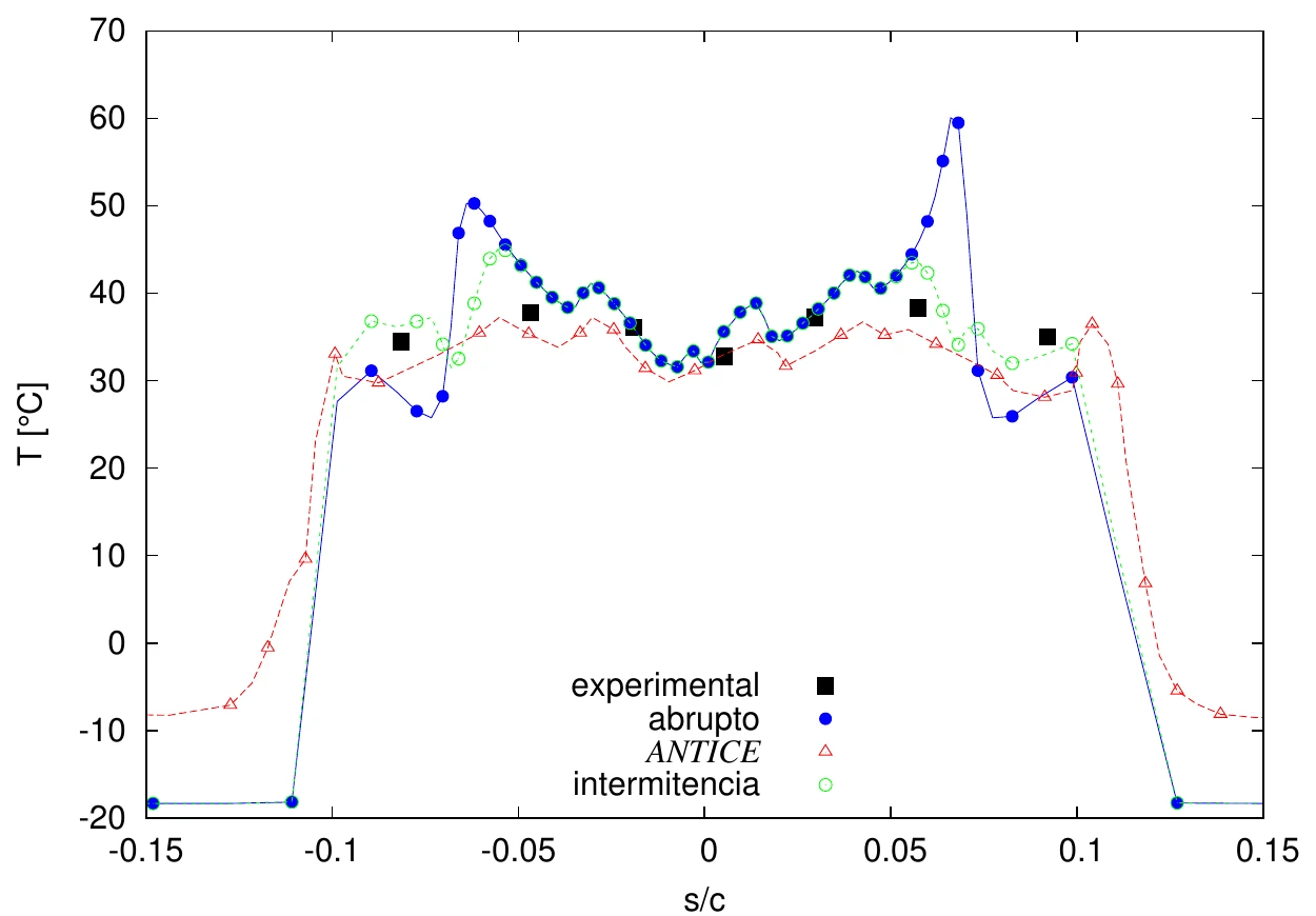
| Anti-ice model against NASA experimentResearch | Surface temperature and heat transfer coefficients against the experiment of Al-Khalil et al. (2001). | ATS integral and differential boundary-layer models. | AIAA, 2009. |
Papers behind the method
- Silva, Silvares, Zerbini (2007). Numerical simulation of airfoil thermal anti-ice operation, part 1: mathematical modelling. Journal of Aircraft 44(2).
- Silva, Silvares, Zerbini (2007). Numerical simulation of airfoil thermal anti-ice operation, part 2: implementation and results. Journal of Aircraft 44(2).
- Silva, Silvares, Zerbini, Hefazi, Chen, Kaups (2009). Differential boundary-layer analysis and runback water flow model applied to flow around airfoils with thermal anti-ice. AIAA.
- Silva, Silvares, Zerbini (2006). Water film breakdown and rivulets formation effects on thermal anti-ice operation simulation. AIAA/ASME Joint Thermophysics Conference.
- Domingos, Pustelnik, Trapp, Silva, Campo (2007). Development of an engine anti-ice protection system using experimental and numerical approaches. SAE.
- Lima da Silva et al. (2011). Proposed wall function models for heat transfer around a cylinder with rough surface in cross flow. SAE 2011-38-0023.
- Souza, Lisboa, Allahyarzadeh, Silva et al. (2016). Thermal analysis of anti-icing systems in aeronautical velocity sensors and structures. J. Braz. Soc. Mech. Sci. Eng.
Examples
Select an image to see each example.
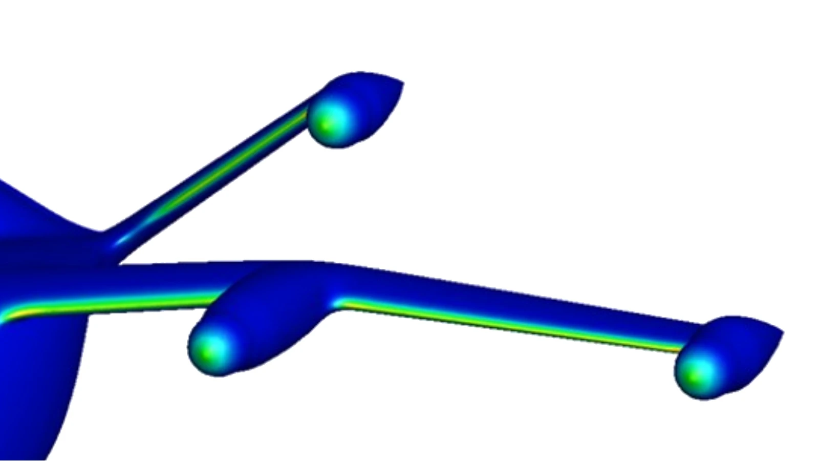
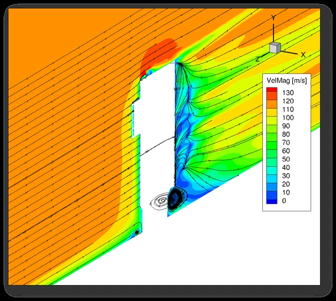
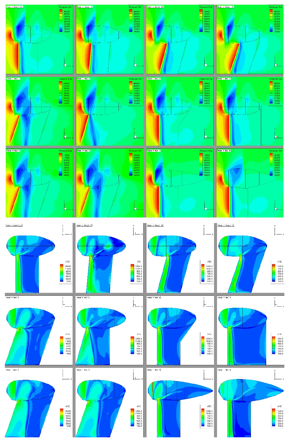
1 / 12
Probe heat load
Heat load against water collected for air data probes, with the requirements of old and current standards.
Request a technical proposalWhat we protect
Wings and empennage
Electrothermal, hot-air and boot systems on leading edges and balance horns.
Engine inlets, ram air and propellers
Ingestion risk, lip heating and blade or spinner protection.
Air data probes and vanes
TAT, pitot and smart probes, angle-of-attack vanes and ice detectors, with heater power and location.
Windshields
Heating for the pilot’s view, with layer stack and temperature limits.
Antennas and radomes
Protection that does not disturb the electromagnetic function.
eVTOL, drones and rotors
Aircraft that may have no conventional system and must show that ice does not affect operation, or that they can escape the condition.
Tests and simulation work together
Tests you will still need
Wind tunnel with simulated ice for aerodynamics, icing tunnel for the protection system, artificial-ice and natural-icing flight tests, and tests that validate the results.
What simulation does for the campaign
It designs the system, saves tunnel and flight tests, supports coverage of the envelope, supports certification and supports the analysis of failure cases.
Where the experience comes from
Ten years of anti-ice design and certification at Embraer, then client projects at ATS, together with research and the development of our own solver.
Industry Embraer, 1997 to 2007Project ATS client and facility projectsResearch Papers, workshops and committeesiceAccretionFoam Development of our own 3D solver
- 1997–2007Industry
Embraer: design and certification of anti-ice for the wing and for pitot, TAT, static port and smart probes, with tests in the NASA icing tunnel and simulation.
E190: pneumatic system, ECS and the icing certification, with its wind tunnel and flight test campaign and reports. E145: probe technical support, ADs, service bulletins and flight manual. E170/190: smart probes certification, an innovative, simulation-intensive job with CFD++, answering an EASA CRI that anticipated in 2003/2004 the liquid water conditions of SAE AS5562, which TSO-C16b only included more than a decade later. Slat and wing thermal anti-ice with LEWICE simulation and tests in the NASA icing tunnel. Also the 2001 probe certification process with manufacturers and authorities, and an engine anti-ice system (SAE, 2007).
- 2003Research
Airfoil anti-ice system modeling and simulation, AIAA 41st Aerospace Sciences Meeting.
- 2006–07Research
Water film breakdown and rivulet model, and two Journal of Aircraft papers on airfoil anti-ice.
- 2007Project
ATS begins engineering, testing and certification services supported by simulation, with icing and ice protection systems projects on probes, wings and eVTOL.
- 2009Research
At Cal State Long Beach, integrated Cebeci’s compressible differential boundary-layer method into his anti-ice code, with the runback water flow.
AIAA paper with Profs. Hefazi, Chen and Kaups.
- 2010Research
Air data probe power density model, SAE AC-9C, Portland.
- 2011–15Research
Rough-wall heat transfer wall functions, then CFD and boundary-layer models with transition validated on a rough cylinder.
- 2016Project
Pitot icing in flight and in the icing tunnel designed for UFRJ, with the thermal analysis of anti-icing in velocity sensors and structures.
- 2020–24Project
Turkish Aerospace STC on a surveillance aircraft: ice-protection substantiation and certification-support analyses (FENSAP based), with simulation and test support, in partnership with Akaer.
- 2023–24Project
Joby (eVTOL): air data probe heat load mapping and 3D water catch, with icing certification support.
- 2023Research
Coupled heat and mass transfer for airfoil ice protection systems, published on the ATS blog.
- 2026–28iceAccretionFoam
iceAccretionFoam: FAPESP PIPE Phase 2 targets thermal protection in the 3D solver.
How an engagement runs
Mission and performance
Mission profile, weights, speeds and altitudes. Angle-of-attack ranges from flight dynamics.
Baseline ice and critical conditions
Ice on the unprotected surface and the critical points of the envelope.
System design
Architecture, heat source, layers, protected area and control logic with your team.
Thermal analysis
Heat balance, water film, runback and power density at the critical points.
Failure cases and residual ice
Ice shapes when the system fails or is off, and the residual ice after de-icing.
Certification reports and test support
System description, safety assessment, certification plan, and reports of the numerical model and of the icing tunnel and flight tests. All under NDA.
Talks, articles and press
- FAPESP approves iceAccretionFoam under PIPE (2026)
- Simulation for airfoil ice protection systems: coupled heat and mass transfer (2023)
- Numerical simulation of convective heat transfer for in-flight icing (2023)
- Aircraft icing explained: interview with Revista Asas (2024)
- “The Icing Engineering Process”: lecture at SUNY Korea (2022)