 Skip to content


In October 2025, ATS4i presented the development plan of iceAccretionFoam, its new three-dimensional CFD code for aircraft ice accretion simulation, at the meeting of the SAE AC-9C Aircraft Icing Technology Committee. The meeting was part of the SAE International Committee Meetings, held from October 20 to 23, 2025 at CIRA (Centro Italiano Ricerche Aerospaziali) in Capua, Italy.
The talk “iceAccretionFoam: Rime and Glaze Ice Accretion” (PDF) was given by Dr. Guilherme A. Lima da Silva, CEO of ATS4i, who attended with Henrique Lewi, the company’s Head of Sales. The project has moved forward since then: the development of the code was approved by FAPESP under the PIPE program and is now under way.
Summary
- Event: SAE AC-9C Aircraft Icing Technology Committee, at CIRA, Capua (Italy), October 2025.
- Topic: iceAccretionFoam, a 3D CFD solver for rime and glaze ice, built on foam-extend 5.0.
- Partnership: collaboration with Prof. Hrvoje Jasak, University of Cambridge, original developer of FOAM.
- Published results: two papers in Philosophical Transactions of the Royal Society A (2025) and one at ICAS 2024.
- Next step: project approved under FAPESP’s PIPE program, with Phase 1 running in 2026 toward the Beta version.
What is SAE AC-9C?
AC-9C is the SAE International technical committee dedicated to aircraft icing technology. Its meetings bring together aircraft manufacturers, system and sensor suppliers, research institutes, academia and authorities to discuss test methods, simulation and ice protection. It is one of the forums where new icing simulation tools are presented to and discussed with the community.
The October 2025 meeting was hosted by CIRA, the Italian aerospace research center that operates an Icing Wind Tunnel.


Why a new 3D icing code?
In-flight ice reduces lift, increases drag and weight and can compromise sensors. Predicting ice shapes is an essential part of safety assessment, ice protection system design and certification.
Many tools treat the problem as quasi-3D: the external flow is 3D, but the water film and ice growth are solved on 2D cuts normal to the leading edge. On swept wings and complex geometries, the shear lines that drive the water deviate from those cuts and the prediction loses accuracy, especially for glaze ice. iceAccretionFoam was conceived to solve the whole process in a single 3D solver, without these simplifications.
Applications go beyond wings and stabilizers: air data probes (Pitot tubes and smart probes), antennas and radomes installed in aircraft modifications, engine inlets, propellers, and the rotors of drones and eVTOL aircraft.
How iceAccretionFoam works
The solver is implemented in foam-extend 5.0 and brings together, in a single code, modules that are usually separate programs:
- Compressible flow: transient URANS (rhoPimpleFoam) with energy equation and kinetic heating.
- Droplets: Eulerian dispersed phase (driftEulerFoam) with droplet size distribution.
- Water film: Finite Area Method for the hydrodynamics and thermal balance of the water on the surface.
- Ice growth: Immersed Boundary Surface method (by Prof. Jasak), which updates the ice shape without remeshing or mesh deformation.
- Heat transfer: rough-wall function and roughness-triggered laminar-turbulent transition.
- Ice protection: 2D shell thermal conduction, planned for anti-ice and de-ice system simulation.

Results presented: rime and glaze ice
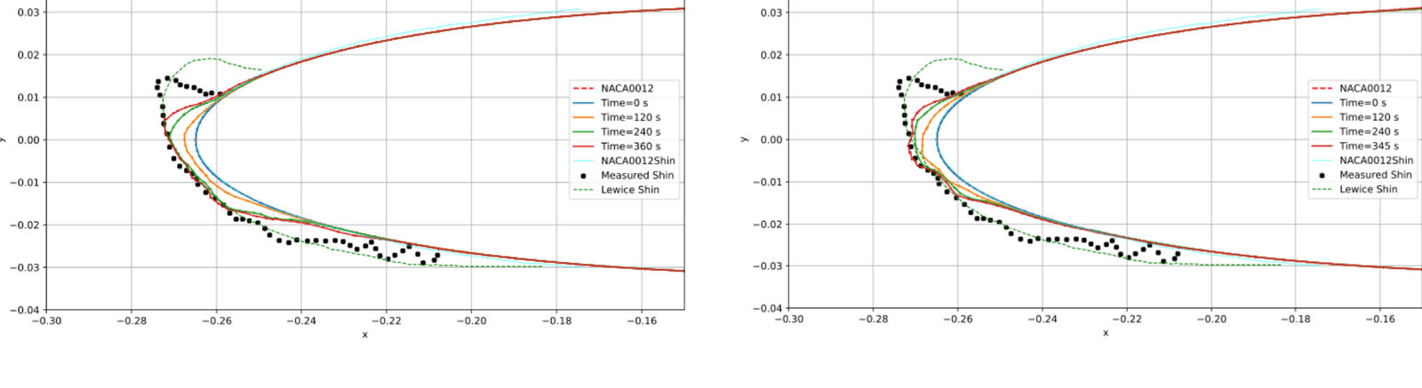
At the meeting, ATS4i showed the evolution of the ice shape on a NACA 0012 airfoil, compared with NASA experimental measurements (Shin) and with LEWICE. For rime ice, the results were considered acceptable and consistent with the experiments. For glaze ice, the predicted behavior is correct and the next refinements are the Messinger thermal freezing fraction, cell mapping that follows ice growth, and heat and mass transfer with transition.

Validation plan and roadmap
Validation follows a sequence of increasing complexity: pressure coefficient (Cp) and collection efficiency (beta), 2D rime ice, 2D glaze ice, 3D shapes and supercooled large droplets (SLD), and finally thermal ice protection systems. The first two steps are complete.

The roadmap shows that the code builds on more than two decades of icing work: a new certification process for probes with manufacturers and authorities (2001), physics modeling in the M.Sc. and Ph.D. (2003), ideation from customer requirements (2019), the choice of OpenFOAM with finite area, immersed boundary and full 3D (2022), and the collaboration with Prof. Jasak on foam-extend 5 (2023/24). The next milestones are the Beta version (2026) and the MVP (2027/28).

Next step: project approved under FAPESP’s PIPE program
After the Capua meeting, the project “iceAccretionFoam: three-dimensional CFD for aircraft ice accretion simulation” (ICE Code) was approved by FAPESP, the São Paulo Research Foundation, under the PIPE program (Innovative Research in Small Businesses), Phase 1, grant 2025/19697-9. Phase 1 runs for eight months, from May to December 2026, along four lines:
- Physics: immersed boundary to finite area mapping, rough-surface heat transfer and laminar-turbulent transition.
- Validation: classic 2D rime and glaze cases compared with experimental data on several airfoils.
- Product: cloud deployment study (SaaS) and an AI-assisted graphical interface.
- Qualification: technical feasibility dossier for Phase 2.
Phase 1 aims to take the code from TRL 3 to TRL 6, with a validated Beta version. Phase 2 targets TRL 8 (MVP), with complex 3D geometries (swept wings, radomes, antennas, engine inlets and eVTOL rotors), SLD and thermal coupling for ice protection systems. The FAPESP project will be covered in detail in an upcoming post.
Team
iceAccretionFoam is coordinated by Dr. Guilherme A. Lima da Silva, principal investigator of the FAPESP PIPE project. In Phase 1, development is supported by two FAPESP Technical Training fellows, a TT-5 (Ph.D. level) and a TT-4A (M.Sc. level), in collaboration with Prof. Hrvoje Jasak, University of Cambridge, who guides the work on the foam-extend core, finite areas and the immersed boundary method. The early phases of the code benefited from the contributions of Jayme R. Teixeira da Silva, Rafael Miranda Hazana Carvalho, Maria Eduarda M. C. Lopes, Augusto P. R. Preguiça, Pedro C. de Souza Villela and Caio F. Rafael, co-authors of the papers published at ICAS 2024 and in Philosophical Transactions of the Royal Society A.
Read more
- FAPESP PIPE: iceAccretionFoam, from 2D beta to 3D MVP: the plan of the project approved by FAPESP.
- SAE AC-9C presentation, Capua, 2025 (PDF)
- Introducing the iceAccretionFoam solver: impingement and rime ice (Phil. Trans. R. Soc. A, 2025) · PDF
- Advancing the iceAccretionFoam solver: glaze ice accretion (Phil. Trans. R. Soc. A, 2025) · PDF
- ATS4i publications
- ATS at NUMAP-FOAM Summer School 2023
- Simulation for airfoil ice protection systems
- Service: Ice Protection and Accretion Engineering and Simulation
- Versão em português
- Numerical Simulation of Convective Heat Transfer for In-Flight Icing (2023)
- “The Icing Engineering Process”: SUNY Korea lecture (2022)
- Handbook of Numerical Simulation of In-Flight Icing (2022)
Frequently asked questions
What is the difference between rime and glaze ice?
Rime ice forms when supercooled droplets freeze on impact, at lower temperatures, producing opaque ice that follows the airfoil contour. Glaze ice occurs closer to 0 °C: part of the water runs back before freezing and forms irregular horns that are harder to predict and more harmful to aerodynamics.
Why simulate ice in 3D?
On swept wings, probes and rotors, water runs back along three-dimensional shear lines. Approaches based on 2D cuts do not capture this flow, which mainly affects glaze ice prediction.
Where can iceAccretionFoam be applied?
Wings, stabilizers, air data probes, antennas and radomes, engine inlets, propellers and drone and eVTOL rotors, both to predict ice shapes and, in Phase 2, to simulate ice protection systems.
Do you need ice accretion or ice protection analysis? Talk to the ATS4i team.


